Main Street, Columbus: Difference between revisions
(Created page with " == Pre-Installation == 300px 300px 300px<br/> This downtown condo had installed the only internet service...") |
No edit summary |
||
| Line 1: | Line 1: | ||
== Pre-Installation == | == Pre-Installation == | ||
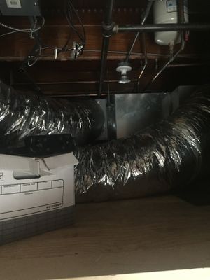
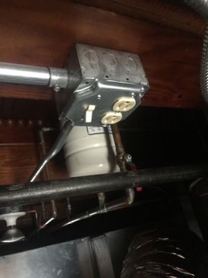
[[File:IMG_8882.jpg|300px]] [[File:IMG_8881.jpg|300px]] [[File:IMG_8890. | [[File:IMG_8882.jpg|300px]] [[File:IMG_8881.jpg|300px]] [[File:IMG_8890.jpg|300px]]<br/> | ||
This downtown condo had installed the only internet service available/provided to the building, a 60/6 MBps cable internet from Spectrum, but was experiencing poor video streaming. The home wanted to leverage Netflix and Plex services, but the building has a very congested WiFi radio spectrum and the interference (note at the bottom of this page, the UniFi access points detected 550 nearby WiFi networks) and distance from the access point to the family room and master bedroom TVs was causing poor (unacceptable) performance.<br/> | This downtown condo had installed the only internet service available/provided to the building, a 60/6 MBps cable internet from Spectrum, but was experiencing poor video streaming. The home wanted to leverage Netflix and Plex services, but the building has a very congested WiFi radio spectrum and the interference (note at the bottom of this page, the UniFi access points detected 550 nearby WiFi networks) and distance from the access point to the family room and master bedroom TVs was causing poor (unacceptable) performance.<br/> | ||
| Line 11: | Line 11: | ||
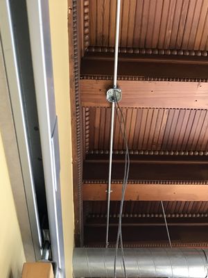
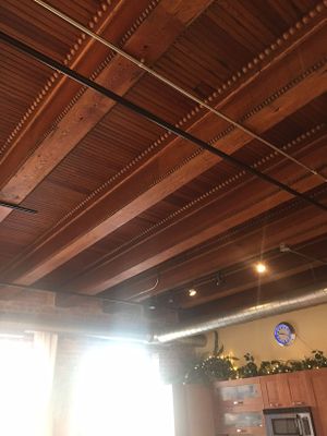
Image:IMG_8882.jpg|Wood ceilings have conduit today, we'll replicate this | Image:IMG_8882.jpg|Wood ceilings have conduit today, we'll replicate this | ||
Image:IMG_8883.jpg|Utility Space 2 | Image:IMG_8883.jpg|Utility Space 2 | ||
Image:IMG_8888. | Image:IMG_8888.jpg|Office before Install | ||
Image:IMG_8889. | Image:IMG_8889.jpg|Utility loft | ||
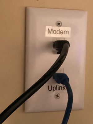
Image:IMG_8890. | Image:IMG_8890.jpg|Cable connections | ||
Image:IMG_8891. | Image:IMG_8891.jpg|And power outlets | ||
</hovergallery> | </hovergallery> | ||
== Planning == | == Planning == | ||
[[Image:Bennett Condo Runs.png|300px]] [[Image:Network_Diagram. | [[Image:Bennett Condo Runs.png|300px]] [[Image:Network_Diagram.jpg|350px]] [[Image:Heat Map.jpg|325px]]<br/> | ||
From here we started building our plan. Based on the approximately 1,500 SQFT of space we chose to go with 2 wireless access points. One might have sufficed, given the very open nature of the main living spaces, but I wanted to make sure we had excellent coverage in the master suite as well. Note that the UniFi access points have a pleasant blue LED shows their connected status, but this is not suitable for a sleeping space. <br/> | From here we started building our plan. Based on the approximately 1,500 SQFT of space we chose to go with 2 wireless access points. One might have sufficed, given the very open nature of the main living spaces, but I wanted to make sure we had excellent coverage in the master suite as well. Note that the UniFi access points have a pleasant blue LED shows their connected status, but this is not suitable for a sleeping space. <br/> | ||
<br/> | <br/> | ||
| Line 31: | Line 31: | ||
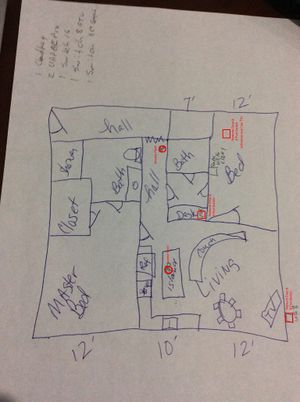
Image:IMG_0005.jpg|Rough Sketch | Image:IMG_0005.jpg|Rough Sketch | ||
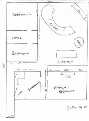
Image:bennett_scale.jpg|Scaled sketch | Image:bennett_scale.jpg|Scaled sketch | ||
Image:Network_Diagram. | Image:Network_Diagram.jpg|Network diagram | ||
Image:Bennett Condo Runs.png| The conduit runs we will install | Image:Bennett Condo Runs.png| The conduit runs we will install | ||
Image:Heat Map.jpg|Heat/Coverage Map | Image:Heat Map.jpg|Heat/Coverage Map | ||
| Line 39: | Line 39: | ||
== Installation == | == Installation == | ||
[[Image:IMG_3842. | [[Image:IMG_3842.jpg|300px]] [[Image:UAP-AC-PRO-installed.jpg|300px]] [[Image:IMG_4798.jpg|400px]] <br/> | ||
Working with Jeff, our subcontractor, we arrived early to do the installation. This unit has quite high (12 ft) ceilings so we brought a variety of step ladders for ease of access. There were a couple of wrinkles to our plan, first the roof beams were slightly more crowded that we expected, so traversing the space laterally was constrained. Also, both walls in the family room are brick, whereas we believed on was drywall covered.<br/> | Working with Jeff, our subcontractor, we arrived early to do the installation. This unit has quite high (12 ft) ceilings so we brought a variety of step ladders for ease of access. There were a couple of wrinkles to our plan, first the roof beams were slightly more crowded that we expected, so traversing the space laterally was constrained. Also, both walls in the family room are brick, whereas we believed on was drywall covered.<br/> | ||
| Line 179: | Line 179: | ||
Hover over any picture for a larger size, or click it for a larger version (or click again for full size).<br/> | Hover over any picture for a larger size, or click it for a larger version (or click again for full size).<br/> | ||
<hovergallery> | <hovergallery> | ||
Image:IMG_3841. | Image:IMG_3841.jpg|Jeff installing conduit runs | ||
Image:IMG_3842. | Image:IMG_3842.jpg|More Jeff | ||
Image:IMG_3843. | Image:IMG_3843.jpg|Pulling wire to network/utility closet/loft | ||
Image:IMG_3844. | Image:IMG_3844.jpg|Junction for | access point | ||
Image:UAP-AC-PRO-installed. | Image:UAP-AC-PRO-installed.jpg|Access point installed, Unifi AC Pro (UAP-AC-PRO) | ||
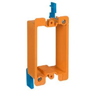
Image:low volt.jpg|Low Voltage box for wall plates | Image:low volt.jpg|Low Voltage box for wall plates | ||
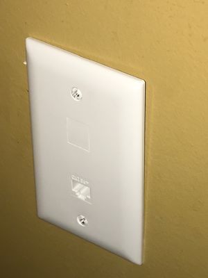
Image:IMG_4793. | Image:IMG_4793.jpg|LaGrand wall plates installed in drywall for bedroom Ethernet access | ||
Image:IMG_4795. | Image:IMG_4795.jpg|Dual wires run to office to feed WAN from cable modem to router, and back to office switch | ||
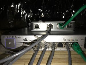
Image:IMG_4796. | Image:IMG_4796.jpg|Router (top-UniFi Security Gateway) and POE core switch (UniFi US-8 150W) day | ||
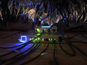
Image:IMG_4797. | Image:IMG_4797.jpg|Router (top-UniFi Security Gateway) and POE core switch (UniFi US-8 150W) night | ||
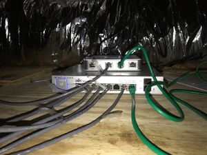
Image:IMG_4798. | Image:IMG_4798.jpg|Router and core switch top view | ||
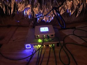
Image:IMG_4799. | Image:IMG_4799.jpg|Router and core switch close-up | ||
Image: | Image: | ||
</hovergallery> | </hovergallery> | ||
| Line 206: | Line 206: | ||
Hover over any picture for a larger size, or click it for a larger version (or click again for full size).<br/> | Hover over any picture for a larger size, or click it for a larger version (or click again for full size).<br/> | ||
<hovergallery> | <hovergallery> | ||
Image:IMG_8888. | Image:IMG_8888.jpg|Cable modem Ubee UVW32CB with phone service | ||
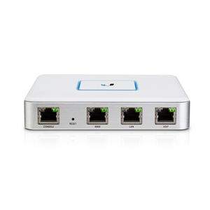
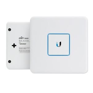
Image:USG3.jpg|UniFi Security Gateway/Router | Image:USG3.jpg|UniFi Security Gateway/Router | ||
Image:usg3-2.jpg|UniFi Security Gateway/Router | Image:usg3-2.jpg|UniFi Security Gateway/Router | ||
Image:IMG_4798. | Image:IMG_4798.jpg|Router and core switch top view | ||
Image:IMG_4799. | Image:IMG_4799.jpg|Router and core switch close-up | ||
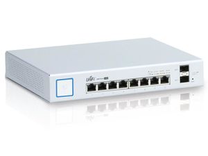
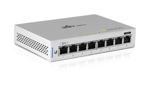
Image:unifi-switch-US8-150W.jpg|UniFi US-8 150W Switch (ports) - acting as the network core switch (all other switches and APs connect here) | Image:unifi-switch-US8-150W.jpg|UniFi US-8 150W Switch (ports) - acting as the network core switch (all other switches and APs connect here) | ||
Image:US-8-150W.jpg|UniFi US-8 150W Switch (front) | Image:US-8-150W.jpg|UniFi US-8 150W Switch (front) | ||
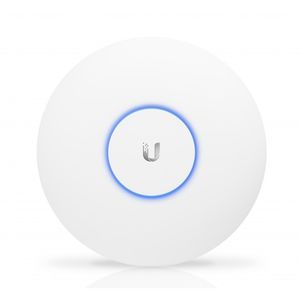
Image:uap-ac-pro_front.jpg|UniFi AC band access points (UAP-AC-PRO) | Image:uap-ac-pro_front.jpg|UniFi AC band access points (UAP-AC-PRO) | ||
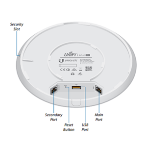
Image: unifiacpro-back.png|Back up wireless access points | Image: unifiacpro-back.png|Back up wireless access points | ||
Image:UAP-AC-PRO-installed. | Image:UAP-AC-PRO-installed.jpg|Access point installed, Unifi AC Pro (UAP-AC-PRO) | ||
Image:Heat Map.jpg|Heat/Coverage Map | Image:Heat Map.jpg|Heat/Coverage Map | ||
Image:UBNT-US-8-1.jpg|UniFi US-8 switches for office, family room, and master bedroom for multiple users (TV, Roku, DVR, etc.) - the distribution switches | Image:UBNT-US-8-1.jpg|UniFi US-8 switches for office, family room, and master bedroom for multiple users (TV, Roku, DVR, etc.) - the distribution switches | ||
Image:UBNT-US-8-2.jpg|UniFi US-8 switches are powered by the core switch over Ethernet to save outlet space | Image:UBNT-US-8-2.jpg|UniFi US-8 switches are powered by the core switch over Ethernet to save outlet space | ||
Image:bennett_scale.jpg|Scaled sketch | Image:bennett_scale.jpg|Scaled sketch | ||
Image:Network_Diagram. | Image:Network_Diagram.jpg|Network diagram | ||
Image:Bennett Condo Runs.png| The conduit runs we will install | Image:Bennett Condo Runs.png| The conduit runs we will install | ||
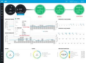
Image:NOC_1.jpg|Network Dashboard/"Single Pane of Glass" | Image:NOC_1.jpg|Network Dashboard/"Single Pane of Glass" | ||
| Line 242: | Line 242: | ||
|[[Image:IMG_8883.jpg|Utility Space 2|thumb]] | |[[Image:IMG_8883.jpg|Utility Space 2|thumb]] | ||
|- | |- | ||
|[[Image:IMG_8888. | |[[Image:IMG_8888.jpg|Office before Install|thumb]] | ||
|[[Image:IMG_8889. | |[[Image:IMG_8889.jpg|Utility loft|thumb]] | ||
|[[Image:IMG_8890. | |[[Image:IMG_8890.jpg|Cable connections|thumb]] | ||
|- | |- | ||
|[[Image:IMG_8891. | |[[Image:IMG_8891.jpg|And power outlets|thumb]] | ||
|[[Image:IMG_0005.jpg|Rough Sketch|thumb]] | |[[Image:IMG_0005.jpg|Rough Sketch|thumb]] | ||
|[[Image:bennett_scale.jpg|Scaled sketch|thumb]] | |[[Image:bennett_scale.jpg|Scaled sketch|thumb]] | ||
|- | |- | ||
|[[Image:Network_Diagram. | |[[Image:Network_Diagram.jpg|Network diagram|thumb]] | ||
|[[Image:Bennett Condo Runs.png| The conduit runs we will install|thumb]] | |[[Image:Bennett Condo Runs.png| The conduit runs we will install|thumb]] | ||
|[[Image:Heat Map.jpg|Heat/Coverage Map|thumb]] | |[[Image:Heat Map.jpg|Heat/Coverage Map|thumb]] | ||
|- | |- | ||
|[[Image:BenNet+.jpg|Installed in the FerrellMedia test rack|thumb]] | |[[Image:BenNet+.jpg|Installed in the FerrellMedia test rack|thumb]] | ||
|[[Image:IMG_3841. | |[[Image:IMG_3841.jpg|Jeff installing conduit runs|thumb]] | ||
|[[Image:IMG_3842. | |[[Image:IMG_3842.jpg|More Jeff|thumb]] | ||
|- | |- | ||
|[[Image:IMG_3843. | |[[Image:IMG_3843.jpg|Pulling wire to network/utility closet/loft|thumb]] | ||
|[[Image:IMG_3844. | |[[Image:IMG_3844.jpg|Junction for | access point|thumb]] | ||
|[[Image:UAP-AC-PRO-installed. | |[[Image:UAP-AC-PRO-installed.jpg|Access point installed, Unifi AC Pro (UAP-AC-PRO)|thumb]] | ||
|- | |- | ||
|[[Image:low volt.jpg|Low Voltage box for wall plates|thumb]] | |[[Image:low volt.jpg|Low Voltage box for wall plates|thumb]] | ||
|[[Image:IMG_4793. | |[[Image:IMG_4793.jpg|LaGrand wall plates installed in drywall for bedroom Ethernet access|thumb]] | ||
|[[Image:IMG_4795. | |[[Image:IMG_4795.jpg|Dual wires run to office to feed WAN from cable modem to router, and back to office switch|thumb]] | ||
|- | |- | ||
|[[Image:IMG_4796. | |[[Image:IMG_4796.jpg|Router (top-UniFi Security Gateway) and POE core switch (UniFi US-8 150W) day|thumb]] | ||
|[[Image:IMG_4797. | |[[Image:IMG_4797.jpg|Router (top-UniFi Security Gateway) and POE core switch (UniFi US-8 150W) night|thumb]] | ||
|[[Image:IMG_4798. | |[[Image:IMG_4798.jpg|Router and core switch top view|thumb]] | ||
|- | |- | ||
|[[Image:IMG_4799. | |[[Image:IMG_4799.jpg|Router and core switch close-up|thumb]] | ||
|[[Image:IMG_8888. | |[[Image:IMG_8888.jpg|Cable modem Ubee UVW32CB with phone service|thumb]] | ||
|[[Image:USG3.jpg|UniFi Security Gateway/Router|thumb]] | |[[Image:USG3.jpg|UniFi Security Gateway/Router|thumb]] | ||
|- | |- | ||
|[[Image:usg3-2.jpg|UniFi Security Gateway/Router|thumb]] | |[[Image:usg3-2.jpg|UniFi Security Gateway/Router|thumb]] | ||
|[[Image:IMG_4798. | |[[Image:IMG_4798.jpg|Router and core switch top view|thumb]] | ||
|[[Image:IMG_4799. | |[[Image:IMG_4799.jpg|Router and core switch close-u|thumb]] | ||
|- | |- | ||
|[[Image:unifi-switch-US8-150W.jpg|UniFi US-8 150W Switch (ports) - acting as the network core switch (all other switches and APs connect here)|thumb]] | |[[Image:unifi-switch-US8-150W.jpg|UniFi US-8 150W Switch (ports) - acting as the network core switch (all other switches and APs connect here)|thumb]] | ||
| Line 283: | Line 283: | ||
|- | |- | ||
|[[Image: unifiacpro-back.png|Back up wireless access points|thumb]] | |[[Image: unifiacpro-back.png|Back up wireless access points|thumb]] | ||
|[[Image:UAP-AC-PRO-installed. | |[[Image:UAP-AC-PRO-installed.jpg|Access point installed, Unifi AC Pro (UAP-AC-PRO)|thumb]] | ||
|[[Image:Heat Map.jpg|Heat/Coverage Map|thumb]] | |[[Image:Heat Map.jpg|Heat/Coverage Map|thumb]] | ||
|- | |- | ||
| Line 290: | Line 290: | ||
|[[Image:bennett_scale.jpg|Scaled sketch|thumb]] | |[[Image:bennett_scale.jpg|Scaled sketch|thumb]] | ||
|- | |- | ||
|[[Image:Network_Diagram. | |[[Image:Network_Diagram.jpg|Network diagram|thumb]] | ||
|[[Image:Bennett Condo Runs.png| The conduit runs we will install|thumb]] | |[[Image:Bennett Condo Runs.png| The conduit runs we will install|thumb]] | ||
|[[Image:NOC_1.jpg|Network Dashboard/"Single Pane of Glass"|thumb]] | |[[Image:NOC_1.jpg|Network Dashboard/"Single Pane of Glass"|thumb]] | ||
Latest revision as of 09:03, 17 January 2019
Pre-Installation
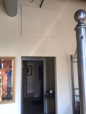
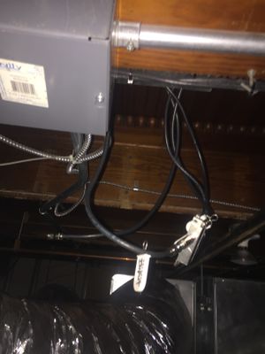
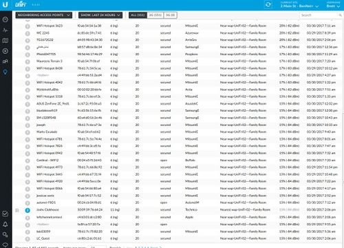
This downtown condo had installed the only internet service available/provided to the building, a 60/6 MBps cable internet from Spectrum, but was experiencing poor video streaming. The home wanted to leverage Netflix and Plex services, but the building has a very congested WiFi radio spectrum and the interference (note at the bottom of this page, the UniFi access points detected 550 nearby WiFi networks) and distance from the access point to the family room and master bedroom TVs was causing poor (unacceptable) performance.
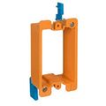
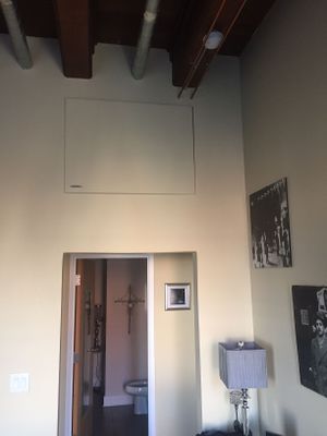
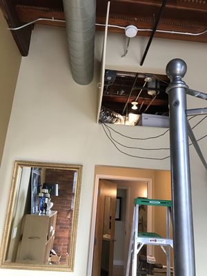
In keeping with the current character of the space, we install new EMT metal conduit for the network. This will keep the low voltage category 5e cabling separate from the possibly noisy power wiring. The utility space already had the cable connection as we as power, so we'll install all of our networking gear in here. We'll use power-over-Ethernet (POE) switches to power everything from this location. This will remove bothersome "wall warts" and wires behind the TVs and on the office desk, while also allowing all of the devices to remotely rebooted by simply cycling the power at the Switch Port.
Hover over any picture for a larger size, or click it for a larger version (or click again for full size).
Planning
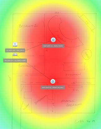
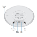
From here we started building our plan. Based on the approximately 1,500 SQFT of space we chose to go with 2 wireless access points. One might have sufficed, given the very open nature of the main living spaces, but I wanted to make sure we had excellent coverage in the master suite as well. Note that the UniFi access points have a pleasant blue LED shows their connected status, but this is not suitable for a sleeping space.
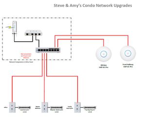
We therefore chose to place this in the hallway, which in this installation also happens to be a lofted utility/storage space. Also, we wanted to provide the absolute best streaming experience to the TV locations, while maintaining excellent connectivity to the office where multiple gaming machines were setup. Therefore we wanted to bring wired connections to each of these locations. This brings the full speed of the internet connection to each primary user, while offloading the wireless traffic and free it up for the users that must be on WiFi (iPads, iPhones, etc.)
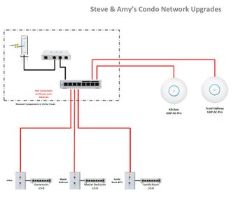
Note that we purchased and installed all of the components and had them running in our testing lab prior to taking them to the client location, to assure a trouble-free install. In the planning phase we chose to leave the cable modem on the office desk, and provide a Ethernet cable from it to the router, and back to the desktop Ethernet switch from the Core switch. This was an accommodation to the fact that we cannot remotely command the modem to restart, which is occasionally required by the end user. By leaving it on the office desk, if the Network Operations Center detects that traffic is not flowing we can simply request the owner to unplug the unit.
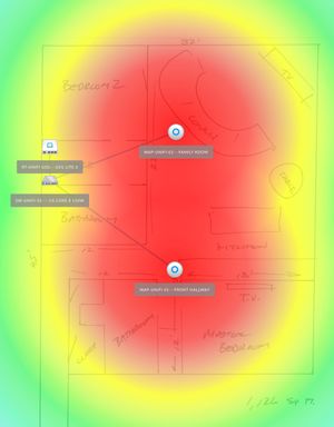
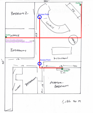
Next we created a scale drawing of the space within the UniFi controller, and place the required hardware on the map, and check the coverage. As you can see the dual access points should provide excellent WiFi coverage to the entire space. You can also see the planned conduit runs across the ceiling, which will then drop inside the walls to low voltage boxes with wall outlets for Ethernet connectivity.
Hover over any picture for a larger size, or click it for a larger version (or click again for full size).
Installation
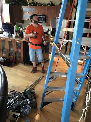
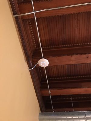
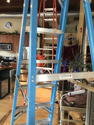
Working with Jeff, our subcontractor, we arrived early to do the installation. This unit has quite high (12 ft) ceilings so we brought a variety of step ladders for ease of access. There were a couple of wrinkles to our plan, first the roof beams were slightly more crowded that we expected, so traversing the space laterally was constrained. Also, both walls in the family room are brick, whereas we believed on was drywall covered.
To accommodate this we elected to make on long longitudinal run across the unit, and place the family room run along the outer wall to reach the back of the TV. This worked quite well, with only one junction at the "T" coming out of the utllity space, and one to mount the family room wireless access point to. From here one additional run was made into the guest bedroom wall for a future TV or computer, but this is not currently used. As I mentioned above, the other access point was placed above the hall in the secondary utility room between the master bath and bedroom. One run continues from here into the master bedroom to drop behind the TV, with a Unifi switch 8 POE for the DVR, AppleTV, etc.
Once pulled all cables were tested before being connected to their end devices and powered up. Once powered up, the existing cable modem WiFi network was deactivated and all traffic moved to the new equipment. We maintained the same WiFi SSID and password so that no users were negatively affected, but a Guest network was also provided with full network isolation. This prevents and infected guest computer or device scanning the main network and potentially infecting our clients devices.
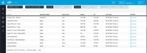
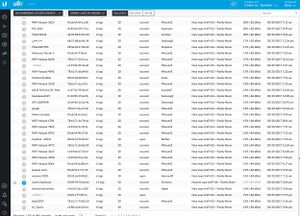
Finally speed and usage tests were made to verify that all wired and wireless clients were connecting at the full available speed. Wired and wireless were able to access the full 60/6 MBps connection speed, a dramatic improvement. Below is a listing of the current connected devices.
|
AppleTV |
Generation 4 |
Family room |
Wired
| |
|
AppleTV |
Generation 4 |
Master bedroom |
Wired
| |
|
ChromeCast |
Family room |
Wireless
| ||
|
Playstation 1 |
Generation 4 |
Office |
Wired
| |
|
Playstation 2 |
Generation 4 |
Office |
Wired
| |
|
Amazon Echo |
Generation 1 |
Kitchen |
Wireless | |
|
Apple iPhone |
7 Plus |
Various |
Wireless | |
|
Apple iPhone |
6S |
Various |
Wireless | |
|
Apple iPad |
Air 2 |
Various |
Wireless | |
|
Android Tablet |
Galaxy Note 2 |
Various |
Wireless |
Hover over any picture for a larger size, or click it for a larger version (or click again for full size).
UniFi Networking
We're using a standard Time Warner/Spectrum cable modem (the old Road Runner service), providing 60 MBps download speeds and 6MBps upload. We only install UniFi hardware for it's price/performance benefits. The cost is "prosumer", but the UniFi controller provides enterprise type central management of all devices.
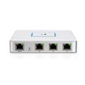
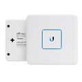
Here we have installed the smaller of the two Security Gateway router products, based on the relatively manageable numbers of connected devices and required networks. Both units can route and gigabit speed, so this gives us plenty of headroom on speed if the service to the building is improved in the future.
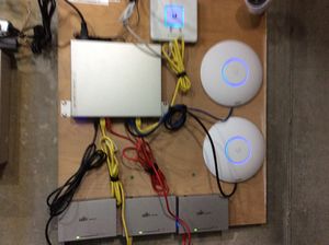
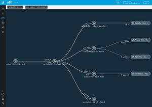
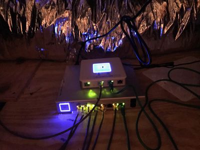
The USG router is connected to a UniFi Switch 8 POE model as the Core switch, providing 150W of power output. This allows us full power management of the networking components, so we could provide uninterruptible power if the incoming source were not power dependent, and it allows us to power cycle all of the connected equipment from the switch if needed. This core switch powers the dual UniFi AC Pro ceiling-mounted (thus the advantage of remote power management) wireless access points off of ports 1 and 2, and 3 UniFi Switch 8's for the office, family room, and master bedroom on ports 3-6. I typically keep port 8 for the uplink, this case to the router.
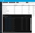
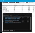
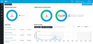
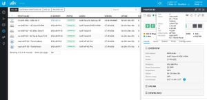
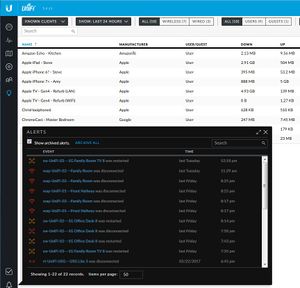
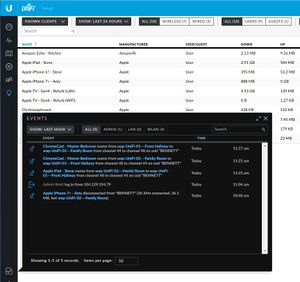
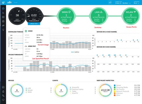
In the pictures below you can see the data available to Network Operations Center (NOC) staff, even on the road via iOS app. We can connect and view internet traffic rates as well as WiFi signal strength, the status of all networking equipment, and reconfigure or reboot them at anytime. This allows us to quickly assess and correct any issues, as well as receive immediate alerts should a fault arise.
Hover over any picture for a larger size, or click it for a larger version (or click again for full size).
Large Versions of all Pictures
For bigger versions of any picture, click the thumbnail.
© Copyright Ferrell Media 2017


